Friday, November 23, 2012

Out of chaos............

cometh order.
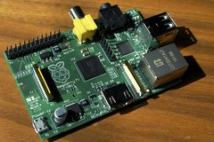
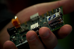
Well, it's on the way at least. The stacking boxes arrived and I have begun the process of filling them. On the same day, the new printer/scanner also arrived and I needed to make room for it so I got half of the boxes up on the bench and filled immediately in order to make that room. In addition, my second Raspberry-Pi also  arrived very soon afterward and I marveled, once again, at the size of it. This coming weekend should allow me a small amount of time to do some more clearing up and sorting even though I am still working in the bedroom at present. I really want to get started on another project but I may take some time to play with stepper motors again now that I have the space to build on.
Enhanced by Zemanta

Monday, November 5, 2012

Still not moving.................

So I decided to do some buying instead. I have built a bed instead of a project but at least I'm sleeping well now. The network problem has been solved so I'm back online again and I have just ordered some small component bins to hold all the parts I have. I live in vain hope that they will solve my space problems. In the mean time, I am trying to keep up to date with the suppliers and projects lists on either side of this. The latest are Cottonpickersplace.com and Manchester uni who are both selling specialist kits to people like us.

Monday, October 15, 2012

Time off can really get in the way of fun!

This weekend was supposed to be quiet and reflective, just the time to use my new soldering station and build a test power supply. WRONG! This weekend was the busiest for months and I only had about ten minutes to myself apart from chatting to Russ. Even now, I still have some major work to do in the house that will keep me away from the soldering iron. sigh.
All the parts have arrived and I'm ready to go................................but I can't yet.

Friday, October 5, 2012

Silence is golden.

It certainly is in this case. Sitting and pondering, just cogitating and thinking, hell, just doing nothing for a few days can bring rewards. I have now got my hands on a better power supply circuit! The older one works well but the small and low cost transformer was just too powerful for the basic circuit and I had to bodge it a bit. The new circuit, has slightly more expensive components and takes up more room but is almost a perfect fit for the transformer and can handle over three amps. I have most of the parts already and now await the larger strip board I think I need to make the first one. I am also waiting for my new soldering station which I have bought in readiness for my retirement.
Enhanced by Zemanta

Tuesday, September 18, 2012

Another breakthrough!

I have added two new links to the 'Suppliers' list on the left. These are Minibloq, a method of programming Arduino and a few other boards in the same way that 'Scratch' works and a source for mechanical robotic component parts. Both of these are open source projects and both look very useful. The hardware even includes a custom Arduino clone especially designed for robotic needs and the software has a very clever method of interfacing directly with it.
Enhanced by Zemanta

Wednesday, September 5, 2012

Or to put it another way,

no I won't. The whole thing has suddenly got much easier, and I will explain why. This is a simple, cheap and very clever board made by Evil Mad Science. Add just five components and 5 volts and you have a working Arduino clone board. All you need are two capacitors, a crystal, IC socket and ready programmed IC. Build your interface on the areas at either end and away you go. Simples.
However, I have had to put everything on hold whilst I work in the bedroom. Hey - Ho.

Monday, August 27, 2012

gottit!

Well, I managed to sort out all the problems I was having with the control board. A wild combination of the wrong components and stupidity. Indeed, some of the wrong components were down to my stupidity so I doubled up there. The switches had seemed just what I wanted when I bought them but turned out to be not quite as robust or well designed as I had assumed. I have had to make several changes to my board in order to make them work.
So
As this is a diary of work done, this is what went wrong.
My first circuit was built on a breadboard and was, basically, only a single channel version to test the combination of hardware and software. It worked well so I moved on to the next stage.
Which was a hard wired version built on a small PCB version of the breadboard. This was for two reasons, firstly I didn't have any standard  Vero board at that precise moment and secondly, I was keen to try out the other type of board. Well, "More haste, less speed" as I made a simple mistake with the resistors and, as they were very close together, it was difficult to spot.
The wrong component problem was that the switches were ideal on paper but not so great in practise. They have a built in LED that has separate leads for the LED and switch connections and that was what was needed for my circuit. They were also cheaper than the only other version I had seen which is sold by Maplin.
So I bought five on the basis that, as I needed four, I would have a spare to cover me damaging one or, hopefully, one to play with after finishing the project. Well, they all arrived damaged due the seller not protecting them for the post. I managed to straighten out all the leads but one of the LEDs was not working so that left me with just the four working items.
My final problem was more to do with inexperience as I hadn't used modern PCBs before and still feel happiest with standard sized Vero board.
I assembled the PCB for the switches and began to check it out, nothing worked so I had to remove some wiring and start again. The copper simply peeled off with the solder so I had to bodge the connections when I reconnected correctly. The wires on the LEDs were too short to reach the other side of the board so I had to wire through the board and then solder at both ends to get a connection. At this point, I was beginning to get somewhat perplexed as, my hastily built PCB test board was working correctly but the carefully wired and set up switch board wasn't and I didn't know why. This wasn't rocket science either, just some very basic connections that should just work. I eventually came to the conclusion that the PCB was compromised and no longer to be trusted. This was a shame, but I still had my original test built on the other board so I wired that in. Success, all the switches worked and two LEDs did. But not the other two. So I began yet another round of checking voltages. I soon sussed out that the two failing LEDs were simply not getting enough power to light them so I traced back to the board and then discovered that my eyesight had let me down. The resisters on the test board were wrong. Only two of course but enough to stop their associated LEDs from lighting. They had been tested on very small low needs LEDs and now I was asking them to power larger and higher needs LEDs, they couldn't cope. So, out with the soldering iron again, swap them for the correct value and, finally, all is working. Now I have to shorten all the wires between the two boards and fit the whole thing into my bench.
Enhanced by Zemanta

Monday, August 20, 2012

It's mounting up..........

With 60 countries and over 2000 individual visitors to the site it seems a good time to run over the philosophy of our open blogger. The idea was, and still is, that it would be used as an open source diary to compliment the various open source areas we cover. These being the Arduino micro controller boards and software and the Raspberry Pi computer and it's software. So far, the Raspi hasn't had too much of a look in as I have been following my plans for the Arduino somewhat single mind-idly  for the past six months. This has resulted in me learning quite a lot about digital electronics though which will be just as useful for the Raspi as the Arduino. I am, hopefully in the final stages of building the finished control unit for my mains switch this week and I have been documenting it with my camera for future publication. Next will be to produce an Arduino work alike to run the switches and a mains power supply for independence.

How about you though? Have you got anything to blog about? Are you prepared to publish it here? If you are then contact me via the comments at the bottom of this post.

Enhanced by Zemanta

Thursday, August 16, 2012

I give in......

My attempt at creating a stand alone Arduino clone of my own has foundered slightly. Whilst the breadboard version worked really well, the hard wired one didn't. I have spotted a few obvious mistakes over the week but none of them have made any difference when rectified. Even more annoying, the test is a simple flash on pin 13 with a time delay of about one second. I can put a meter on the connections and it is registering the timer perfectly. The problem appears to be with the LED, except that the LED works fine elsewhere. I am beginning to lose it with this circuit. In fact, I have decided to go back to the drawing board and build the breadboard circuit up again. This time, I will extend the outputs to several LEDs and see how they affect the performance. In addition, I may put a regulator on the breadboard as well to be certain about the power capability of the whole unit.

Tuesday, August 14, 2012

All but one

of the UK orders have now arrived. He seems to have a genuine excuse as he has proof of posting. Equally, I have proof of non-arrival as all items are sent via the post room who keep a record of everything delivered. Anyway, he will chase Royal Mail from his end and I will keep an even closer watch from my end. The Hong Kong order should be here by the end of this week or the beginning of next week if past results are anything to go by. However, it wouldn't surprise me to hear that the Olympics held up all packages through Hong Kong as their Postal Service always has a ready excuse for non delivery. Fortunately, the trader who posted to me is well known to me and I trust them.

Thursday, August 9, 2012

Rollin', Rollin', Rollin', Rawhide!

The components keep arriving but not the ones I'm waiting for. I have also noticed that the order to Hong Kong which is not due yet but will arrive pretty much on time and complete in all details is due in next week. All of the UK sourced components are trickling in and are now all later than promised on eBay. Three of the four UK suppliers have made some sort of mistake in the order and, either I have had to email them or they have found the problem themselves and sent an apology email. I'm not particularly annoyed by this, just puzzled by why British companies are able to get such a simple process wrong but a Chinese company gets it right every time. There are, of course, some UK suppliers who get it right every time (Thanks Bob) but very few in my own experience.

Tuesday, August 7, 2012

Houston, we have five volts!

Yes, it's true. The power board works a treat and produces the requisite five volts to power the controller. Next, I will have to build a slightly more powerful power unit in order to be able to run the LEDs and the relays. It would also be better to run the soldering tools with a triac switch but, for now, the relays will suffice. Whilst I am waiting for the correct strip board I am loath to do much else but I might build a controller on one of the special boards I bought.

Friday, August 3, 2012

Work

has begun on my mains powered switching system, the first of the transformers have arrived and been tested. They are exactly what I hoped for so next I will be checking out the bridge rectifier and voltage control electronics. The next job then will be to build a strip board version of the breadboard circuit and make it all work as one unit. You may be wondering why I am so keen on using mains for this particular job. In fact, not just mains but a home brew mains unit. The answer is very simple, this unit is intended to be built into the supply chain for my soldering irons, Piranha lights and screwdriver chargers. To do this and remain green, I want to have something that, when switched off, is completely isolated from it's power supply and doesn't need to be charged or new batteries added every so often. As I have more than one project in mind here, it would seem to be a good idea to manufacture my own system and build it into the various boxes instead of running it from a wall wart. There is also the fact that it should work out cheaper, I will be learning and it will be a lot more fun this way. 
4 diodes bridge rectifier
Enhanced by Zemanta

Monday, July 30, 2012

A useful weekend

I have moved my PC workstation to it's new home and almost all of the electronics materials as well. Next will be the Raspberry Pi kit and the satellite PVR to their new homes and then I can start the great tidy up. I hope to reach a point where I can empty the big green recliner and move it to it's new position by next weekend. Once I've managed that, it should be downhill to a tidy and very orderly attic.
Enhanced by Zemanta

Friday, July 27, 2012

Finally,

English: Solder station (used to support solde...
I did some long overdue tidying up in the attic yesterday. I found several items that had mysteriously disappeared, including the FM tuner, and managed to collect half a bag of rubbish. If I keep this up, I should soon be looking at a tidy worktop with all the room I need for my experimenting. This week I took delivery of three soldering iron stations for my three different irons and my new portable multi-meter for a more accurate approach to setting up projects. I am waiting for a delivery from China now to complete my kit of ready made units, tiny stereo amps etc. This weekend would seem the ideal opportunity to get down and really sort it all out. I have, at last, begin to work on the totally integrated micro-controller system I want to build for my own use and have sourced the switches and major components already. The software system I outlined previously is likely to be the basis for what I build but I am progressing with my C. skills and hope to be using function calls to make life simpler. As always, any achievements will be flagged here and documented on the code site. The build will be fairly simple but might involve, I hope anyway, a custom PCB. 
Enhanced by Zemanta

Saturday, July 14, 2012

Slowing down slightly,

I have played with the circuits and code today. The code all seems to work but the very basic breadboard circuit is not working for everything. I am fairly certain that the problem lies with having no regulation on the power. Feeding it from a USB source is all very well but there are serious limitations to the current available and I think I am simply overloading the circuit.
Enhanced by Zemanta

Friday, July 13, 2012

O M G !

I have just built, in less than ten minutes, a working Arduino on a breadboard. Now I know that a large number of clever people are doing this all the time but...............................I just did it too. I really will have to document this over the weekend. I also have some code already written for the super-duper deluxe mains switch I postulated yesterday. I may even build the thing! I may even build it on my own circuit board O M G !
Enhanced by Zemanta

Thursday, July 12, 2012

The most worrying statement I know.

"I've had an idea..........................."
The switch system I built is intended for my low power mains tools, soldering iron, small drill and chargers. Today, I was looking at a piece of kit - expensive kit - that ran a timer on mains operated equipment and switched it off after a pre-set time. And I thought, "I can do that". So, what about a switch that you hit which immediately switches on your soldering iron, for example, and then counts down for 30 minutes and switches it off unless you switch it off yourself. Then, what about a similar system that flashes the led and beeps at you for 30 seconds before auto switch off and if you push the button in that time period it switches the circuit back on for another 30 minutes. Then what about if you add a dual seven segment LED to that with the countdown in minutes. Then how about a short period after the first push where you can increment the timer, on the display, to whatever time you like up to 99 minutes. This is beginning to sound very sophisticated eh? Might do it one day though.
Now you can understand why I'm worried.


English: Solder station (used to support solde...Enhanced by Zemanta

Monday, July 9, 2012

Not only

have I finished the ISP (In system programmer) shield, I have also tested it and....................................it works. This was certainly not the most complicated build I have attempted with the Arduino, but it is very satisfying as I now have a home built tool for further learning and designing. I can recommend the one I bought, from Evil Mad Science. My next project will be the 'Slice of Pi' board and then it will be back to the DIY cloneduino for a bit of knockabout fun. In the meantime, I will be looking at the FM radio board and interfacing that with an Arduino.
Enhanced by Zemanta

Friday, July 6, 2012

Three down,

one to go.
The five volt LED was faulty and the replacement works fine so only the 'working' LED now needs checking. I also assembled the ISP shield from 'Evil Mad Science' yesterday and that's almost ready for testing now.

Wednesday, July 4, 2012

I hope it's only

a small problem. The new board is working fine apart, it seems, from a couple of minor details. The power leds are supposed to reflect whether all the various voltages are working correctly. The twelve volt one does and the 3.3 volt does. The other two are not, however. This could be for any number of reasons so I will have to investigate thoroughly when I next get the time. Oh bother! (Or words to that effect!)
Enhanced by Zemanta

Tuesday, July 3, 2012

A new direction?

Sort of.
I have been building the new Arduino 'work alike' from R K Online Store. It's an interesting board, with a lot of thought having gone into it. The build was fairly straightforward although it would have been easier if my eyesight was better. I didn't get around to a proper test when I had finished but I hope to do some quick testing this evening. As you may have gathered, I am now able to use the new bench and I have cleared yet more space in the attic as well. I have been a busy boy and things are beginning to go in my favour at long last. Once I have this board working, I will be hoping to use it for a somewhat larger project than I have so far attempted. The playing and testing will, of course, continue.
Enhanced by Zemanta

Thursday, June 28, 2012

Almost there.............

Andy Williams song.
The bench is nearly finished, just a couple more things to do. I have received most of the goodies I ordered this week including the Raspberry Pi starter set from S K Pang (see suppliers on left). This is a very well made piece of kit that holds the Pi in place beside a breadboard. The set also comes with the components for an interactive game and a few other useful bits and pieces to make use of the GPIO interface. There will be some more about this soon.
Enhanced by Zemanta

Tuesday, June 26, 2012

Well,

the old desk has gone. Tonight, I begin assembling the new bench.
I have also, some more bits and pieces due soon. I have a supply of 10k resistors and some through board pins ordered and also a Freeduino type board with a prototype area and without a chip. It takes the same chip as the Duemilanove so I will be burning and swapping a bit with that one. I also ordered a zif 28 pin socket so that I could make up a writer unit from one of my Duemilanove boards. When I have that working, I will post details in case anyone else wants to follow the same path.
Enhanced by Zemanta

Sunday, June 24, 2012

Success!

And on both fronts.
I have now completely finished the switch unit and all works very nicely. In addition, I am very close to finishing the basic build of my new bench system. The bench will take a little longer to complete because I have to remove my existing desk and everything in and on it first. This will almost certainly take longer than the final build will, hey ho. Nonetheless, all the parts have now been manufactured and the assembly should be very simple once I get that far. Whilst this isn't the most complicated structure I have ever made, it is by far the biggest free standing piece I have ever attempted and also looks pretty elegant as well. There will be a photo soon.

Thursday, June 21, 2012

Coming along nicely

I finished the full version of my control unit yesterday. It still looks a bit scrappy but is very solidly built and works as I want it to every time. On switch on, it has a minor flutter whilst it finds itself and then settles down to all off. Each button pressed once switches on its related relay and, on the second press, switches it off. I only needed this for four relays but the system is good for six without any changes other than adding more connections to the interface board and a few more lines of code to the sketch. To expand it further will require some extra chips as well. My next move on this theme will be after I have built my FM radio and have that working. Both of these projects will qualify for testing with a DIY built setup just using components on a circuit board. As I haven't been too well for the past couple of days, I am hoping to spend some time this evening sanding the upright supports for the bench in the attic. Once that is done, I will be able to set up the first of the two units and get a lot of my equipment either stored under or on the new worktop. From then on, it should be a fairly speedy journey to completely finishing the whole unit and making a large amount of free space in the attic. I have also 'inherited' from my son and daughter-in-law a large screen TV with plenty of inputs so that will soon be sitting up there and working to at least two computers.
Enhanced by Zemanta

Wednesday, June 20, 2012

Sometimes,

you get a bit of good news.
I was having a bad time with my back/hip yesterday evening and decided to try the chair in the attic. As I was there anyway, I had a look at the sketch for the relay control unit and I now have a working script for up to six outputs with LED tell-tales. Once I have the hardware built, tested and working every time I will publish the script on our Google code site.
Enhanced by Zemanta

Monday, June 18, 2012

Sadly,

the other Debian version isn't too great either. There are known problems with it for some people and I am once again part of the some people. Still, it's hardly a major problem at present so I will just get on with the rest of my plans for the Pi.
The supports for the bench (part one) are now made and, apart from a bit of sanding down, I'm ready to begin assembling it. This should make my life a lot easier in both the short and the long term.

Friday, June 15, 2012

I'm in the majority then.........

XBOX Media Center Logo
The media OS failed again so I am now in the happy position of being one of the many who can get no satisfaction from it. However, tonight I will try out the Debian-XBMC OS as it stands a much better chance of running and installs in the same way as the standard one. If everything comes together as I wish this weekend, I will be constructing the first set of uprights for the bench and, hopefully, mounting the first part of the worktop on it up in the attic. From then on, I will have more room and a lot more freedom to play with the toys...............

Oh and one more thing. The title of this blog has been changed, very slightly. This is to reflect the addition of the Raspberry Pi into our area of interest and the possibilities of linking the two systems together.
Enhanced by Zemanta

Wednesday, June 13, 2012

Kewl

As Todd would say. The other boards and Duemilanove controllers arrived today and I have already got one of the Arduinos running its intended sketch on a breadboard. I also ran off a copy of the media install for the Raspberry Pi but that wasn't quite so good as it had something missing in the built version. I have re-installed it but I suspect I may need to download the software again. I have also ordered a case for the Pi today and that should be on it's way by next week.

Tuesday, June 12, 2012

Well I thought yesterday was good but...............

Then today came.
And so did my Raspberry Pi.
I am currently preparing an operating system for it and then I shall attempt the first boot up.
I also ordered a couple of Duemilanove Arduinos and some Adafruit pcbs from Phenoptix and they may well be here this week. Life is good.
Arduino Duemilanove
Life is even gooder! The operating system worked perfectly first time and I have the Pi running on my Hi Def TV. The resolution is amazing. Yes, the speed of application execution isn't as good as the quad core that I'm typing this on but wow! it's still pretty good and it has such fantastic graphics and it costs so little.English: Extract from Raspberry Pi board at Tr...

Enhanced by Zemanta

Woohoo!!!!!

It works!
Thanks to Jack Christensen, I now have not only a working switching system but also a very simple and elegant one as well. Judging from some of the responses to my forum post, this has been a problem for quite a few people and Jack has created a library to solve the problem. Well done him! I am now in a position to build my proper test unit and explore the possibilities. I must also get that bench built.

Monday, June 11, 2012

Frustration!

I am still having problems with my 'simple' piece of work to toggle some relays on and off by using the same switch. I have spent more time on this one than I did getting an unknown LCD display to work on an Arduino.
I went to the official forum at the weekend and have three answers so far. None of them has made a difference. The problem has to be in my hardware but I simply cannot see how I could make a mistake on such a simple circuit. This morning, the new push switches arrived and I will get a few made up as breadboard switches as a priority in order to try again.
I have also bought the first pack of wood I need to make up the bench in the attic so I will, hopefully, begin that job this week.
Enhanced by Zemanta

Sunday, May 20, 2012

Raspberry Pi now a reality?

Yesterday, I was able to order a Raspberry Pi from RS. It may well be with me within two months. Wow!

Thursday, May 10, 2012

Another milestone

Raspberry Pi
We have just hit our first 1000 visitors. Not bad for such a small, tightly focussed blog. At the same time, 44 countries have now come to look and I have added the Google Translation Service to the side panel, top right. From now on, you will be able to read this blog in your own choice of language. Ian and I are still working on our own projects with some success but I now need my work bench even more than before. I am off on holiday soon so there will be no work done for about three weeks but, upon my return, I will be forging ahead as fast as I can. Also, by then, I may be able to get my hands on a Raspberry-Pi to play with. The first thing to be done when I return will be to buy the wood to build the supports of my bench. Once that is done, I will be able to move forward with the work that needs to be done in a nicely structured way, I hope.
Enhanced by Zemanta

Tuesday, May 1, 2012

One more for the pot...........

I have added another supplier to the list on the left. This is CityNight209. I have been buying from them for quite a while but was wary of adding them to a recommended list due to some of the problems they and I had with delivery. I have put them in now because I am certain that any problems I may have had with deliveries were not of their making. You will see that, in fact, most of their negative feedback is from people who didn't communicate with them first. I did and ended completely satisfied with my goods and their service. Buying from China isn't for everyone, I understand that, but if you make allowances for distance and  cultural differences, the end result is that you can buy the same - or better - goods at much cheaper prices. The down side is a longer delivery period. I have no problem waiting as long as I am dealing with a good supplier, that's why I buy from CityNight209.

Monday, April 30, 2012

Oh, arduino it!!!

I have just spent two hours attempting the most simple thing imaginable and failed miserably. All I want to do is to toggle an led on and off with one push of a button. This is, essentially what the 'De-bounce' sketch does. Just not for me.......I can get the led to toggle on ok, it just won't toggle off for me. I have followed the instructions to the letter, I think, but no joy. Anybody got any bright ideas?
I should mention that I am using a Nano 328 for this but I cannot conceive that this should make any difference.

Friday, April 27, 2012

Where did they go?

The eagle eyed amongst you will notice that VIVID STOCK have disappeared from our list of suppliers we recommend. This is because they have left Ebay and we have no other address for them. There seem to be no suspicious circumstances, they have simply left without any reasons being given. 

Monday, April 23, 2012

Weekend of work...........

but not on the workbench. I spent most of the past weekend being technical in the attic and on the terrace but not one bit of my time was spent on the workbench. Cables galore and a sat dish were re-jigged but nothing else. Hey ho, I will get there soon, I promise.

Monday, April 16, 2012

Good things come..................

to those who are prepared to wait.
The blog is attracting many more visits now than we originally expected. Both Ian and I have been working a little too hard to be able to do as much as we wanted to with our personal projects but we will be getting around to them as soon as we can. As we both work at Plymouth University, and the university is currently going through a very busy time, the best we are able to do at present is to keep this blog up to date. One thing to mention in passing, is the fact that the Raspberry Pi is now beginning to ship and should be with us fairly soon now. More when we have one. The number of visits has now passed the 800 mark with 37 countries checking us out, thank you all for visiting us. The running total I have been keeping above the map is now closed as it takes a lot of time to keep checking and, recently, I have been missing some visits. So, from now on, the map itself will be the only record.
Enhanced by Zemanta

Thursday, April 12, 2012

After a short break,

Shrink wrap
Shrink wrap (Photo credit: Wikipedia)
here we are again. I was in need of a break to recharge the batteries and so we had a short holiday visiting friends and relatives. Upon returning, I had received another accelerometer and a pack of heat-shrink sleeves to help with my projects. I also made some plans to finally rebuild my attic room into some sort of a happy place with computers, a small workshop and a test area for the trundle. As it looks as though I might have a quiet weekend coming, it may happen quite soon.
As you may see above, we have now hit 35 countries that have looked at this blog. It would be good to know that you all intend to return on a regular basis. This, however, will depend on the content provided. This blog is not just for Ian and myself, it was always intended to be open to all. If you would like to contribute to it yourself, please email us and we will enable you to do so.

Wednesday, March 28, 2012

And now it's gone!

After yesterdays depressing post, it's good to be able to report a 'whoop-de-doo' moment for a change. The kit that hadn't turned up yesterday arrived this morning and is wonderful. The company concerned had already offered to send another set of kit but were as pleased as me to discover that, once again, the postal services had delayed delivery. The items received were a couple of integrated infra-red sensors and a 'Piranha' LED board for illumination purposes. I am hoping to use it for photography but it may well fit into several other niches as well. As it is a twelve volt device, it may make a very good reading light in a car, for example.

Thursday, March 22, 2012

A worrying trend.

Emblem of Hong Kong
For many years now, I have bought items from Hong Kong with no problems whatsoever. Unfortunately, since the end of 2011, a number of items have gone missing in the post. I buy, mainly, small electronic components and boards and I have so far lost two packages completely and another two that should have arrived by now but haven't. I have not given up hope of these as yet but the earlier two have never turned up. I must stress that this is not the fault of the respective suppliers in any way. In both the previous instances, they immediately sent replacements free of charge. The suppliers I deal with tend to be the most reliable on Ebay and I certainly have no complaint about them. The original losses occurred during the holiday period of the Chinese New Year and I assumed that this was the reason for the losses. This time, however, the New Year is well over and things should be back to normal. Another worry is that the missing items this time around are from one of the suppliers who had a package go astray last time and the paranoid part of me is wondering if someone is targeting their customers for some reason. Time, I assume, will tell.

Monday, March 12, 2012

Just call me Snowden or Bailey!

A Ginsing mounted on the Duemilanove
I have now begun my photographic library of component parts for Arduinos. Most of the weekend was spent setting up the studio in a box, taking the pictures and then putting them into the Wiki on the Google Code site. Quality was as good as I had hoped for and easily acheived with my new(ish) camera and accessories. I have substantially increased the page count of parts and will be adding some written descriptions and explanations over time. If anyone else feels that they could contribute to this work then, please, get stuck in! It's hard work for one and the more people contributing, the better.

Thursday, March 1, 2012

A damp squib?

To be fair, not in some ways. The vast amount of publicity generated yesterday would, no doubt, have pleased P T Barnum. He was of the opinion that all publicity is good publicity. However, I suspect bad publicity can erode the publics trust in a product as well. Yesterday was not the unqualified success that I would have wished for the Raspberry Pi. There is  a fuller explanation in my diary blog and it will probably explain why I am somewhat concerned about what happened yesterday and, to a certain extent, is still happening today. The main foundation site is still only a simple html page for safety reasons and the two distributors, Farnell and RS, have no boards to sell as yet but have accepted orders for all 10,000 on the way from China. This will be the last time I mention the Pi until I have one in my hands.

Tuesday, February 28, 2012

Raspberry Pi!

Raspberry Pi pre-release board
 (Photo credit: jared_smith)
A bit of digression never hurts, I suspect that most Arduino enthusiasts will also be very interested in the RasPi project as well. Raspberry Pi is a very small 'real' computer destined for the educational market. However, the initial release of ten thousand, due tomorrow, is aimed at developers and people like us. The major attraction is the size, about the same as a credit card only thicker, and the price, currently set at about $35.00. The attraction to us will be the possibility of interfacing the little board to Arduino projects in such a way that the whole electronics unit is inside the robot or whatever. Imagine a number of individual servers running on Arduinos being managed by a RasPi with keyboard and mouse on a Bluetooth link. Or maybe a robot with all the articulation and protection automated but being steered by a master brain  called RasPi.

Monday, February 27, 2012

Just like Christmas.....

I got two major deliveries today,the Ginsing board arrived and I have been playing with it this evening, very nice. Also, I now have a photo bag studio, or whatever, thing. You erect it, stick whatever you want to photograph inside and it acts as a self contained studio for taking good quality photos. I shall be trying that out maybe tomorrow.

Friday, February 24, 2012

Is there a problem?

testando la app di flickr per android.
Image via Wikipedia
As I wrote in the previous post, I have had some difficulty with the LCD shield that I am testing at the moment. The shield itself is fine, very well made and works really well but.................... It seems that none of the sketches in the current libraries will even compile let alone upload to the Arduino. The older library sketch works really well but has no connection with the rewritten LCD library as far as I can see. In addition, there seem to be many variations on the basic shield and although many are listed with proven pin outs in the wonderful Arduino Shield List, my shield is not listed under the name I bought it as. I bought my shield from Vivid Stock of Hong Kong and they don't offer a demo script themselves. Many other Chinese vendors appear to sell the same shield but there is no guarantee that they are identical. Has anyone reading this bought one of these shields, particularly from Vivid Stock, and got it working on the latest software? If so, please post your sketch here so that we may all benefit from it.

Tuesday, February 21, 2012

Back on track

I was over the moon when the LCD shield arrived. The I discovered that there were several problems involved in using it. There are updated libraries for it but most of them won't run on the LCD if you don't know which pins are used for what. In addition, the older libraries only work with older versions of the software. So after some thought, I have set up the previous version of the software and I am using it to test the shield. I have to report that it's excellent!
Enhanced by Zemanta

Monday, February 20, 2012

A cautionary tale.

My two Arduino Nano V3 boards arrived this morning. As I always do, I tried to upload 'Blink' to them as a test. No chance, they may as well not have existed as far as the software was concerned. I was getting the, "avrdude: stk500_getsync(): not in sync: resp=0x00" error. I checked around the forums and got several differing solutions to what seems to be a very well known problem. It's not Nano specific by the way. I tried most of them until I saw a post from someone who had simply updated his drivers. As I am on the latest version of the software, I had thought to be on the latest drivers as well. It would appear not, however, as once run in from the self installer all was well and everything now works as expected. The Nanos are very small and I am expecting to have a lot of fun with them quite soon. In addition, this mornings post brought me a very useful shield with both push switches and a 16x2 display already fitted and ready to go. It's going to be used for testing purposes on the new yellow trundle in order to speed up the design and software development.

Monday, February 13, 2012

Colour change for test trundle!

I have reviewed my testing for code changes over the weekend and decided to move the servo tests to a previous chassis that's now nearly ten years old and very yellow. It's bigger and heavier but has a large, flat surface for mounting the electronics and can carry dry cells very easily. I will be providing pictures of the new (old) chassis soon. The power supplies and ultrasonic sensors have now arrived so I will be getting down to some serious coding for them very soon as well.
I have also set up a Google code site for the sketches. There will mainly be simple snips of tested code that I have written myself to test and demonstrate what I am working on. I will, however, put any larger sketches I write there as well because they will be both open source and tested to work. The site is listed under 'Links to Projects' on the right.

Wednesday, February 8, 2012

Making the Trundle go forward

This is the code so far developed, not very complex yet but I have managed to make two continuous servos run in opposite directions and, so, to 'trundle' along.


// Trundle 1
// by codfangler
// This code is in the public domain.

#include <Servo.h>
Servo myservol;   // create servol object to control left servo
Servo myservor;  // create servor object to control right servo
                             
int posl = 0;       // variable to store the servol position
int posr = 180;  // variable to store the servor position

void setup()
{
  myservol.attach(9);     // attaches the servol on pin 9 to the servol object
  myservor.attach(10);  // attaches the servor on pin 10 to the servor object
}

void loop()
{
  for(posl = 0; posl < 180; posl += 1)    // goes from 0 degrees to 180 degrees
  for(posr = 180; posr < 0; posr += 1)  // goes from 180 degrees to 0 degrees
                                                            // in steps of 1 degree
{                                
    myservol.write(posl);              // tell servol to go to position in variable 'posl'
    delay(15);                              // waits 15ms for the servo to reach the position
}
{  
    myservor.write(posr);              // tell servor to go to position in variable 'posr'
    delay(15);                               // waits 15ms for the servo to reach the position
}
}
As the acrylic tube arrived simply to check sizes
After cutting to size and adding slots for wire


Simpler wiring by using a motor shield with  two servo outputs

Tuesday, February 7, 2012

Thank heaven for little.....

Trundles.
Sometimes, it's just good to be right. I fitted all the parts together, ran a sketch and I have a working trundle.
It can't roll across the floor, as the tiny Nano boards haven't arrived as yet, but everything is working and fits perfectly. YES!
Photographs, constuction details and code will follow soon.

Testing the acrylics.............

The various small test pieces of plastic arrived this morning. First impressions are that they seem to be much more robust than anticipated.

Monday, February 6, 2012

Bumper bundle!

Table of a Shift register
Image via Wikipedia
If you know the source of that title, you must be as old as me.
This mornings mail brought a motor shield, a voltmeter, a long shaft 10mm drill bit, two servo mounting templates and 20 74HC595 shift register chips. This should make life very interesting. The drill bit is for some precision holes on the Trundle and the shift registers will help me make a very simple visual display look really cool, anyone for Knight rider?

Friday, February 3, 2012

Behold, "The Trundle"!

Imagine a tube, 50mm diameter and 100mm long. A wheel on either end but not central, closer to the edge and driven by an adapted servo. The centre has a smaller, 10mm, tube embedded through it and the connecting wires exit through here. Initially, this will be a stand alone buggy that will steer and travel by the use of the wheels alone. This will require a weight in the bottom of the larger tube in order to keep it in the correct position relative to the wheels. Control will be, hopefully, by a Bluetooth system  and should be fairly simple to manage in this first incarnation. The trundle will then become a test bed for most of the basic scripting requirements.
If you look up Trundle on the web, you will find it is the name of a hill fort. My use of the name is based on the concept of a wheeled vehicle that 'trundles' along.

Thursday, February 2, 2012

I plough a lone furrow..........sigh.

I really didn't want this blog to be all me so I recruited Ian to add his two penu'th to it. However, he has younger children than me and they interfere with his efforts on an almost daily basis. Rugby being the most obvious area of time consumption. Nonetheless, he has begun a project, at long last, and will shortly be writing up his experiences here.
My researches got a boost yesterday when I found my missing tiny servos and my electronic calliper. I have now worked out, in my head at least, how to build the trundle units.
The trundle is a small two wheeled buggy intended to be used on the end of a leg of the larger control unit. It will, however, have it's own 'brain' and have some self protecting capabilities.

Wednesday, February 1, 2012

Wither the Duemilanove?

Mine arrived yesterday and I checked it out when I got home. I was very impressed by the size and the fact that it ran my sketches straight out of the box. I know that it's obsolete now but you can still buy them for a very good price if you know where to look. I have also ordered a couple of Arduino Nano clones from China and, when they arrive, I should be in a position to set up some sort of network test as well. My biggest problem at the moment would seem to be the chaos caused by the Chinese New Year celebrations. I have quite a few items ordered and paid for - and sent as well - that have just not arrived yet. The suppliers are being very helpful and will re-send the goods if they haven't arrived by next week so I won't be out of pocket. I will, however have lost quite a lot of time on my project. Speaking of which, I have reached the point where I want to name it and have hit a stumbling block. My original name was, "Self Protecting Autonomous Machine" but that isn't really the impression I want to give so I have opened the name thing up to anyone who cares to make a sensible suggestion. I will publish the usable ones and, hopefully, use the best for the project. Simply post it as a comment below.

Tuesday, January 31, 2012

Ever decreasing circles.

I have resurrected my old buggy from several years ago, removed the OOPIC boards from it and temporarily fitted the Mega 2560 Arduino board complete with breadboard in order to evaluate the two servo motors and my sketch writing for future use. The idea is to run this buggy on servos and the other one on motors and try to work out which is the better for my project. The servos may be more powerful than the motors but they are also more expensive as well. On the other hand, the servos will work directly from the data pins and the motors will need a controller board as well. Plus, of course, the servos will be reporting their position back all the time and the motors won't. All of these factors will have a bearing on which system is chosen. My current roadmap is to build one two wheel trundle to the chosen method and gradually work up to a system using two of them on either end of a long-ish beam. The trundles will steer by way of their two wheels and the front and rear sets will both be autonomous  in some ways. Parallel to this, I will be developing a remote control system using Bluetooth in order to run the non autonomous stuff. Currently though, my buggy is running around in circles as I have not yet got my sketch correct for the servos and they are both running anti-clockwise. As one faces east and the other faces west, you can probably see where there might be a problem.
Arduino Mega 2560
Image by Snootlab via Flickr
Servomotor (Servomechanism)
Image via Wikipedia
Diagram of a Solderless Prototyping Board (Bre...
Image via Wikipedia


Kardoma:

fills the stage with flags!
Free counters!